
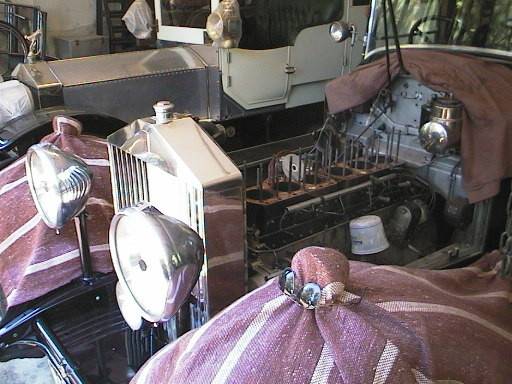
Phantom II heads are made of an aluminium alloy and are quite prone to corrosion. The head on 1930 Phantom II 147GN was showing a slow water leak into the middle exhaust port. We knew that the wall between the exhaust chamber and the water jacket was very thin because of a severe overheating ten years previously. This was repaired temporarily in late 1997.This time we removed the head and had the thin areas TIG and MIG welded back to the appropriate thickness. The following is a record of the reinstallation of the repaired head.
 147GN caught with her cylinder head removed.
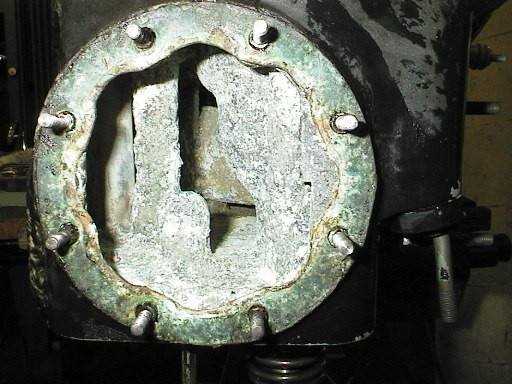
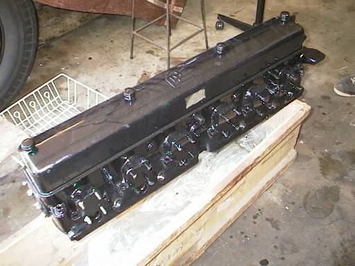
 The newly welded, cleaned
and pressure-tested head.
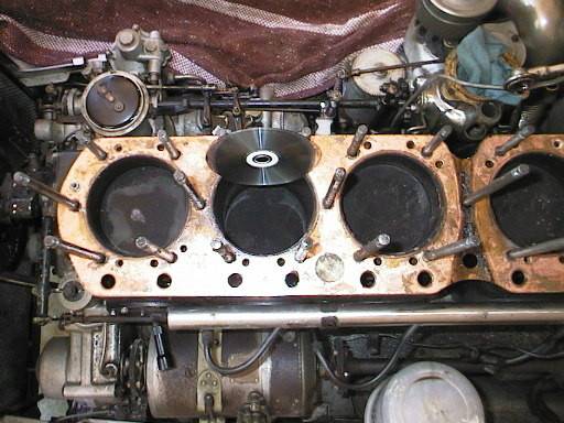
Note the CD for scale.
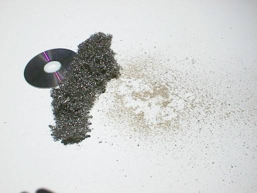 Startling evidence of corrosion:
the grit (RHS) has been caught
in the stainless steel mesh
placed in the inlet to the radiator
as a means of filtering out corrosion products from the coolant.
 A closeup of the corrosion products.
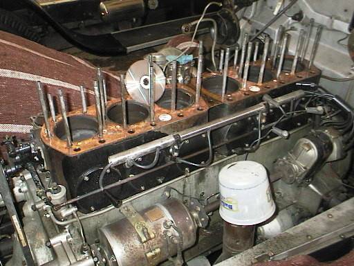
 The scene inside the cylinder head
water galleries, front end.
 This is inside a cylinder head,
not a coral cave!
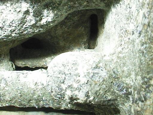 This looks more like an ancient
Indian pueblo cave than a cylinder head.
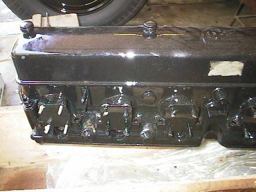
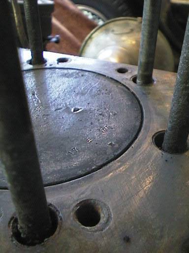
 The centre area (shiny surface in the middle near the CD)
covers where the
The centre area (shiny surface in the middle near the CD)
covers where the
repairs were made to the exhaust port
wall. Some pinhole leaks
have been peened over and will
later be filled in with steel epoxy.
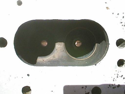 Close up of inlet and exhaust valve seats.
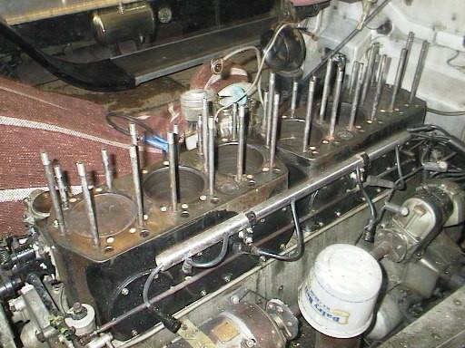
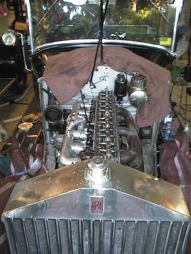
 147GN with the head removed.
Note the CD for scale.
 The blocks with the old gasket
still on. Note the CD.
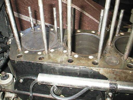
 A downwards view of cylinders
1,2 and 3. Note the CD.
These are big cylinders!
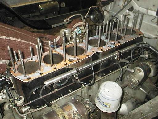
 The view of the blocks from the
intake side. Note the carburettor with
the rag stuffed in the downpipe.
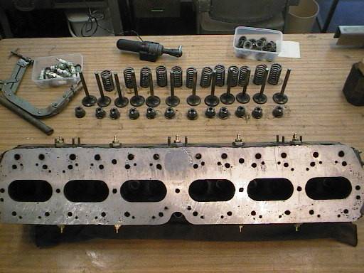 All valves and springs are numbered. The
valves need to be lapped in before assembly.
 This is the spare head. It was
brought out for comparison, in
case it was better than the current
one. It wasn't, primarily because it has had more repairs.
 Closeup of the spare head. Note
that all openings are blanked off
to minimise corrosion in storage.
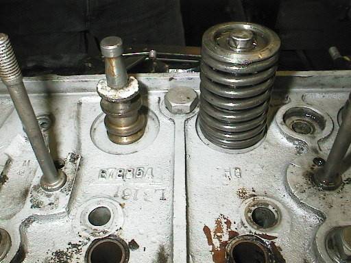
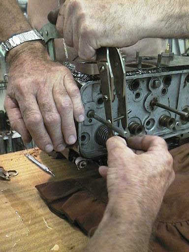 Assembling a valve spring. Can
you really get the collets in
horizontally?
(Note the welding ripple on the upper
face: that's 1/4" of refacing,
puddle-welded by hand.(
 It seems that two pairs of
hands can successfully do it.
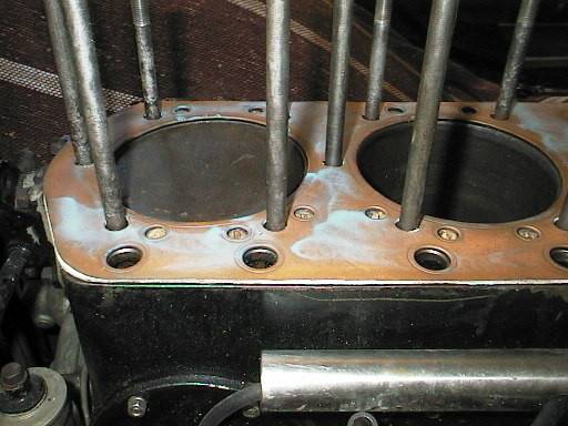
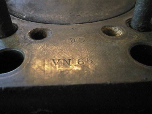 The block faces have been cleaned.
It's a good opportunity to check your
numbers. This is the correct
block/engine number for 147GN.
 Evidence of a foreign object
in number 5 cylinder.
These pistons were fitted C.1977.
 Another view of the face of piston 5
Is 17 6 77 a date?
 Another foreign body impact; this
is on piston number one, in much
the same position as that on number five.
 A change of orientation for
assembling the valves.
 Valve and oil seal in place.
Note the teflon wrapping at the top.
This will end up compressed
under the cap.
 Hammering down the valve seat.
 Valve stem oil seal cap in place.
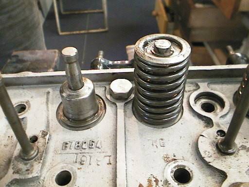
 Drop the valve spring over the
valve stem and place the cover
plate on top.
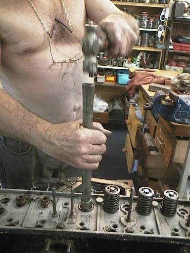
 Compressing the spring. This is
still a two-person operation if the
head is not secured to a bench.
 Spraying the new head gasket
(the old one might have done
just as well) with Hylomar soft gasket cement.
Leave it for a while.
 The cleaned block face is
now ready for the gasket.
 Detail of the clean block face.
 The head gasket is on. Don't
forget to liberally coat the head
bolts with a high-temperature
lubricant/anti-corrosive. We used
"Never-Seez".
 Detail of the blocks with
head gasket in place.
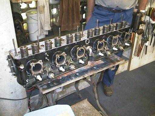 The mighty Phantom II cylinder
head: ready for installation.
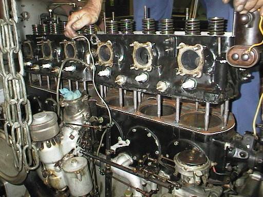 You have to push the head bolts
around to get them all through their
holes. When you do, watch out! The
head may just drop! Here the head is
resting on a couple of the last set of bolts.
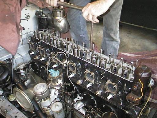
 After pushing a few more bolts around,
the head sits neatly. The next thing
to do is to persuade the pushrods to go
down. Some need jiggling and some need
a little more 'persuasion'.
 Tightening the head . We use a torque
wrench because we don't have a small
Mancunian mechanic around to 'feel the
weight'. We chose 28 foot pounds this time around.
We don't want any leaks.
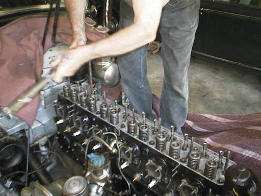 Once more around with the torque
wrench. We'll do this again in a
week or so.
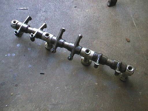 The rear rocker arm can go on now,
as can the front. Be sure to align
the shafts so the oil channels are
in the right way up.
 The intake manifold is ready to go
on. We'll clean the contact faces
first, though. A soft wire wheel
does it nicely.
 There are twenty-four studs for
the intake manifold, which means
a lot of washers and nuts. Some of
them are in pretty awkward places as well.
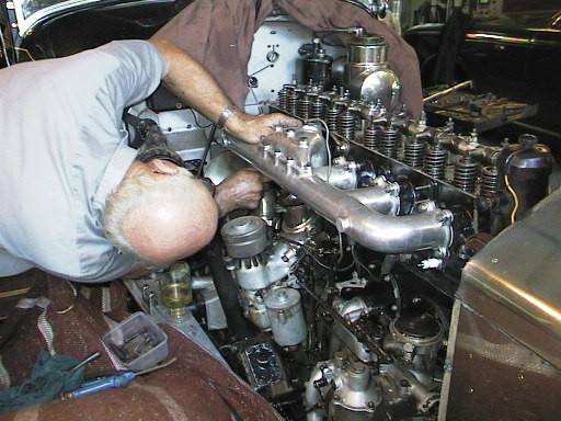
 The exhaust manifold is a lot
less complicated. Once bolted to the
head, the downpipe is moved into
place with a trolley jack.
 We've almost finished the
intake manifold bolts, now.
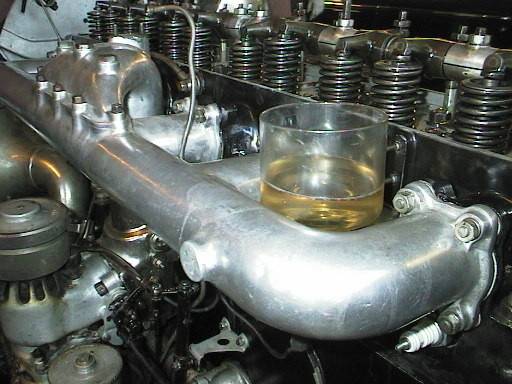 In true Rolls-Royce style, there's
even a place to put your champagne
glass.
 It looks like the exhaust
side is all done.
 Apart from some electrics and
the starter carburettor pipe,
we're just about finished.
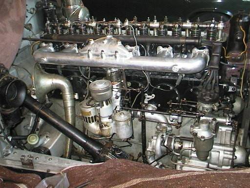
 The view from the front.
It's not so naked, now.
 A few minor adjustments, on
with the rocker cover and we're done.
 Except, of course,
for the starting carburettor.